Mercedes 190sl Weber Conversion
The Mercedes 190sl was equipped with a 1.9L inline 4 fed by 2 Solex PHH 44 carburetors. These things are complicated, expensive and of course troublesome. For one, the front and rear carburetors are different on cylinders 2 and 4, having a vacuum operated venturi of sorts on the second barrel of each unit for smoother running and better response. They worked fairly well but there were a lot of steel parts wearing against poor quality aluminum. Things would start getting loose as the independent throttle shafts wore, venturi's worked loose and they grew further and further out of tune as people tried in vain to adjust them or rebuild them with absolutely no success.
The other major problem was the inability to withstand a lot of heat, warping the body causing the venturi problems and misalignment of the throttle shafts for starters. The exhaust manifold is directly below and between them. What did they think was going to happen? Many a 190 has received long term garage duty over these. They are truly a nightmare. There are 2 versions; one is cast (Germany) and the other a Mikuni version made of light alloy. Both had problems and there's one guy in Germany that has the equipment and know how to fix them, and it will only cost you around $6,000 bucks. You can buy them used all day longh but it’s usually Mikuni or junk, most often junk. You’re just buying a problem. If you don’t have the capacity to repair the body and get the 4 throttle shafts aligned, they will never function correctly. We use one of the best machinists in the World and he said “You’ve got to be kidding; this is almost impossible. He could do it but it would cost between $15,000 and $20,000.”
So, in steps Weber (Redline) with a bolt on kit with universal linkage and adaptor plates for the plenum. The Weber’s bolt right on and look good. It soon becomes apparent that neither the original or universal throttle linkage will simply bolt on. Don’t bother calling, they won't know.
The second problem was the adaptor plates. They give you those tin redline air filter assemblies, but you can't do that! It's a Mercedes! The minor installation issue is the fuel lines and it’s only an issue of appearance. Make a template out of fuel line with the tees and banjos included and take it to a commercial or industrial brake, hydraulic or hose maker. They can take care of you.
None of this is really that big of a deal. The plates require a milling machine and some welding skills. Farm some of it out. Follow this picture tutorial to see how to fix it and make it look fairly original. Tuning might be your biggest headache but I’ll Walk you through it without all the myth and lore.
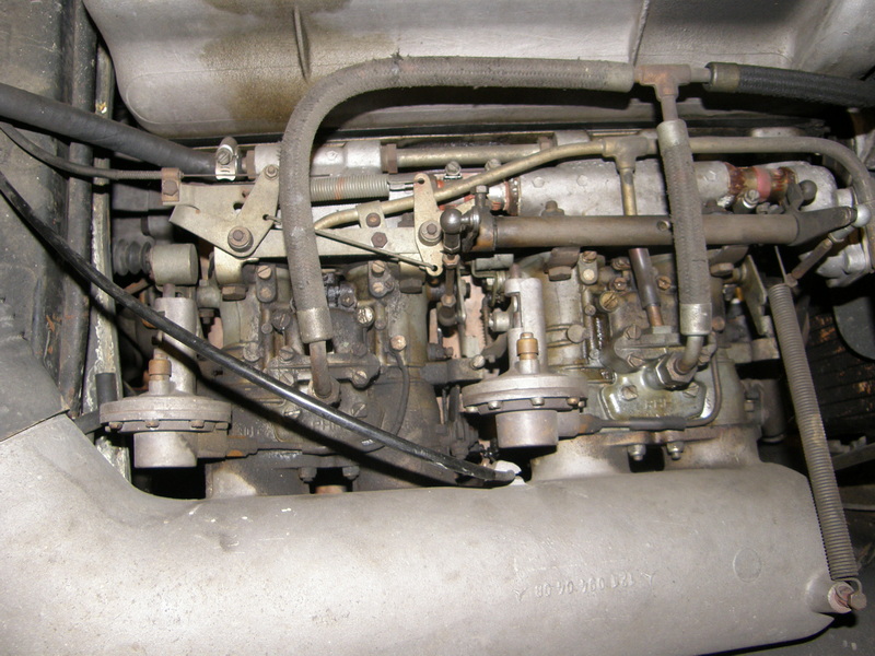
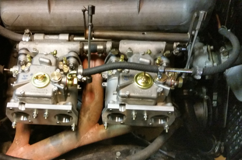
This is what your original carburetor setup should look like:
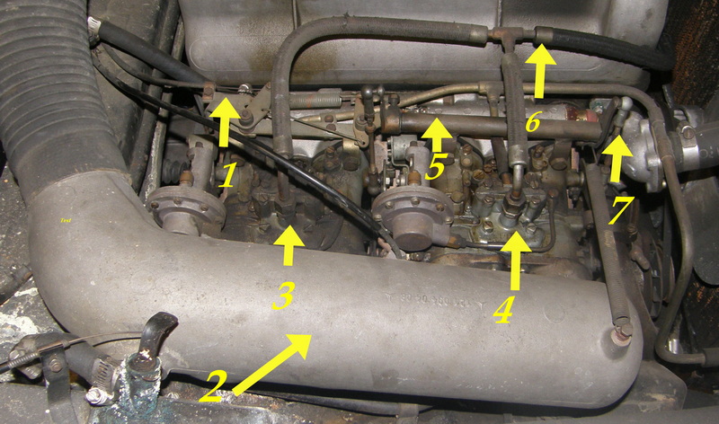
- Colds Start/idle enrichment linkage 2) Plenum 3) Rear carburetor and metal fuel line 4) Front carburetor and metal fuel line 5) Pivot Assembly 6) Machine crimped fuel line and T 7) Primary linkage rod.
Separate everything from the carburetors, you're going to need some of it. The plenum isn't going to fall off. See the 6mm studs and nuts from the top with a wave washer, flat washer and a nut? Same on the bottom, and no, your arm won't fit in from the side, back or top. Reach through the front. There's a bracket from the base of the plenum to the engine block. This one can be reached from the side. It should be a 9mm x 1.5 (15mm wrench) The one the block is a 10mm x 1,25 (17mm Wrench) Just loosen it until the bracket swivels out of the way. Then about 3 hours later, you have the Plenum off and carburetors in your hands.
Sell them on E-bay and quickly close your account. Seriously though, you can sell them broken. They already know. People buy them for parts all the time. It’s better you just keep them if you’re going to sell at any point. I add $4000 to the value on appraisal if they’re just present, $10,000 if they’re on the car and working correctly. It’s one of those ‘Is what it is’ things. No carburetors, plenum or air cleaner? I deduct around %7,.500.
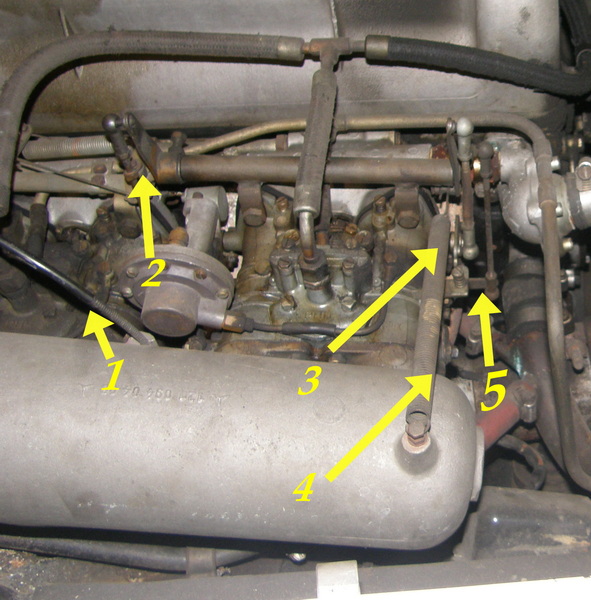
- Choke Cable 2) Pivot Arm 3) Carburetor Throttle Linkage 4) Throttle Return Spring 5) Primary Throttle Linkage Rod
Your first problem is going to be the throttle rods. As in all of them. Follow the adjustment instructions precisely at the end of this article. The primary throttle arm is going to get hung up on the back of the thermostat housing and also hit the exhaust manifold directly, no avoiding it and adding base plates to the Webers won’t do either. The plenum won’t fit because of the adaptor plates for that fit to the top. The plenum is more important. So, set the linkagee rods aside for now. Install the pivot assembly and arms first. Temporarily install the throttle rods to the carburetor and the pivot arms. ‘Zero’ the pivot arms to full stop rest. Turn the hard stop carburetor idle stop screws counterclockwise until they don’t make contact then back out another 1.5 turns, (These are on the side and affect the throttle plate, not the idle air mixture screws.
Install the rods loosely from the carburetors to the pivot arms. Loosely means no resistance. Make sure the throttle plates are fully closed. Do the front carburetor first, adjusting the pivot arm not the rod. Activate the throttle by turning the fulcrum. It should travel the exact distance from closed throttle plate to fully open and stop. If it doesn’t, the rods need adjustment. Adjust the rod so the throttle plate has the correct length or amount of travel (90 Degrees). The rod will bind and the plate won’t open fully if it’s wrong. Leave the rod on and connect to the pivot arm first. Do the same and don’t move the plate on #1. When everything slips together, put the clips on the rods and secure them.
Turn the idle air screws in until they hit a soft stop. B.ack out 1 ½ turns. Leave them for now.
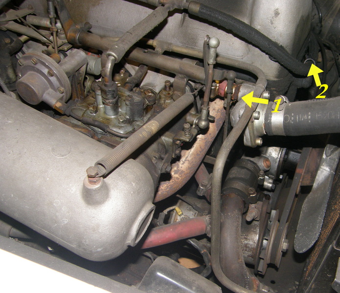
- Primary, Linkage Rod 2) Metal Fuel Line to Pump
The metal fuel line should already be off at the pump, it’s last to install on the top of the carburetors. Start with the primary rod on the bottom. The linkage runs along the side of the block. Connect the bottom rod and attempt to connect it tp the pivot arm. 1” below where it hits the manifold, put 22.5 degree bend, then another one about 1” away when it clears the pipe. As you go above the pipe, bend inwards, then up. Measure the pivot arm, cut and thread, the left hand thread goes to the bottom so you can rotate the rod. You will still have to remove it to adjust it. Same method as before, everything zero and slips on no resistance. Adjust the travel of the rod with the ball end If you cut the rod the correct length it will need minimal adjustment.
The fuel fittings come with the kit. With the metal fuel line off, you can dry fit it and bubble flare the other end of the it as close as possible to the T on the front carburetor. There will no longer be the U shaped metal lines for the carburetors, just the one line and no return from the Webers. The choke cable will need the vinyl sheathing partially striped away to fit the bosses cast on the 45 DCOE. the choke is internal, so no flap. See last image for cable location.
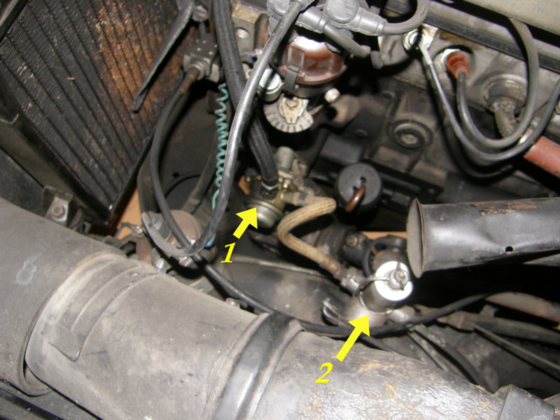
1) Manual Priming Fuel Pump 2) Reserve Fuel Switching Valve/filter
I highly recommend replacing or rebuilding the pump and doing the same with the reserve switching valve/fuel filter. Inspect both closely for leaks or blockage in the valve. You may have trouble finding the primer pump, they’re frequently out of stock.
This job was a no start after replacing the carburetors. After rebuilding the fuel pump and the valve, still no start. Added fuel and vroom! A week later; dead again. What happened was that the pickup tube, which is rather long, had rusted through right at the ½ Tank level. It took a little time to figure out. A new fuel tank immediately solved the problem. The metal lines were replaced for good measure. The car had been sitting for some time and we did clean the tank first. Now we clean the tank or replace the and put only one gallon of gas rather than filling the tank. Just something to be aware of.
Get familiar with your Webers
Weber carburetors are relatively simple but tuning can be a little challenging. Don’t be tempted to start changing jets, air correctors or emulsion tubes, it ain’t the problem to put it bluntly. Don’t start turning screws without knowing procedure because tain’t the problem neither.
So, if you have problems, start with synchronization. Make sure that all of the throttle plates are opening and closing equally. Mixture screws are even, and the throttle stop screws are not holding the throttle plates open. 90% of the time, these are your Weber woes be it one carburetor or six. Another item yo can check is the float level. Pull the top, measure from the gasket to the front edge of the float. It is 5mm closed and 15mm full open on any Weber, that’s 10mm of total float travel. Less will vapor lock you, more will flood you. That’s a little about Webers. Follow the instructions below and DON’ T TOUCH THE JETS.

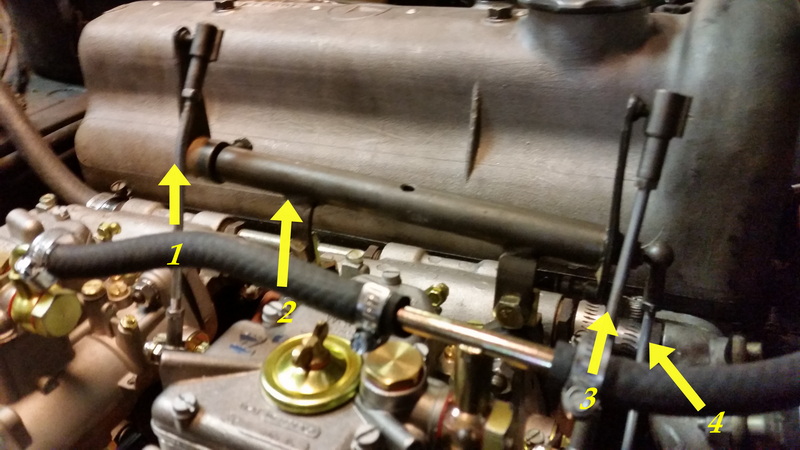
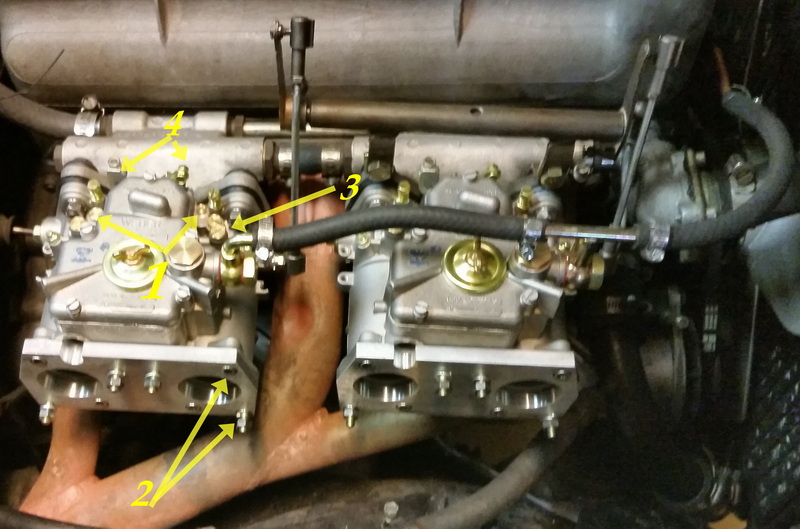
- Idle Air Bypass 2) Idle Air Corrector & Jet 3) Air Bleed Screw 4) Choke Securing Screw 5) 3/16/5mm x 1,0 Throttlle Rod. LH thread at one end. Required bends are marked.
After the linkage is properly set, step one is to verify that the throttle stop screws are not contacting the throttle shafts. These are not idle screws. See the last image for location. Disconnect the linkage rods from the carburetors and start the engine. It will run if you remembered to back out the idle air bypass screws 1 ½ turns. Start at the front and turn the idle screw in until it starts to run rough. Back it out slowly until it runs rough again. Adjust the screw in until you get the smoothest idle. Do the rest. I go through twice. Adjust the throttle stop screw until it contacts the throttle shaft cam, turn it ½ turn. If you set the bypass screws correctly you will be spot on. Some linkage kits have adjusters between the carburetors to balance the idle. Avoid this if possible and vacuum sync them to get your idle correct. There are several ways to do this a uni-syn or carburetor synchronizer works ok. Ideally you buy the Weber tool and use a 4 port synchronizer. The weber tool screws in right above the mixture screw where the flat brass plug sits. Insert the tool for each port and connect them to the 4 port vacuum gauge. You can now tune the idle mixture screws and the air bleeds simultaneously to set the idle perfectly. The air bleeds will correct high or low idle as well as uneven idle. Use the stop screws to fine tune the idle speed. Do not turn them more than ¼ turn either direction. If you need to, something is off, go back. Connect the throttle linkage, and test drive. Repeat the procedure if it’s not correct. If it’s still wrong, check ignition, compression etc. DON’T TOUCH THE JETS.
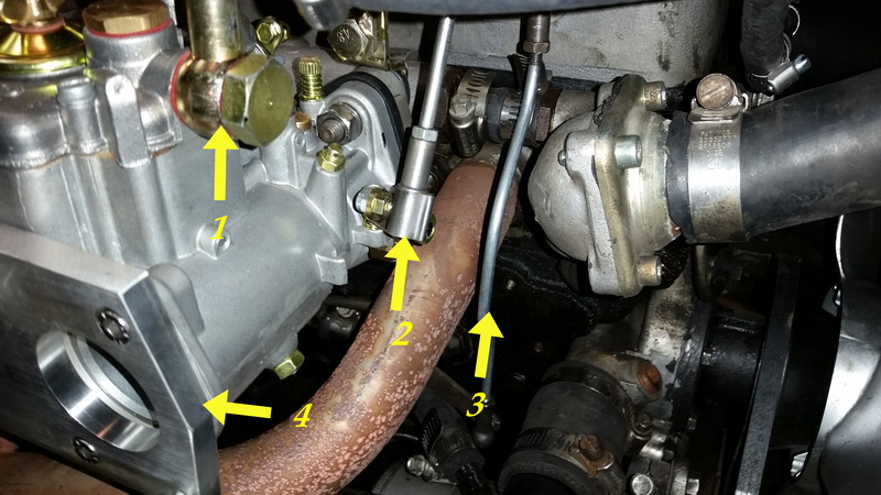
1) Fuel Inlet Banjo 2) Throttle Rod 3) Primary Throttle Rod 4) Plenum Adaptor Plate
1) Rear Carburetor Throttle Linkage Rod 2) Pivot Arm Assembly 3) Front Carburetor Linkage Rod 4). Primary Throttle Linkage Rod
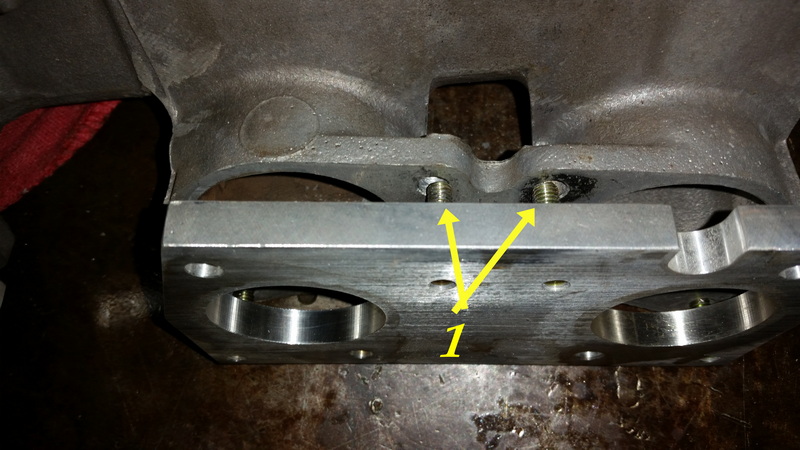
`1) Plenum to Carburetor Adaptor Plate
Entirely different problem here. The adaptor plates came drilled wrong. The holes had to be welded, plates milled, relocated and rethreaded. Sent it all to the machine shop. I assume they have fixed this problem.
Weber Tool for vacuum connection $100 each is what they get for them.
1) Plug (Brass) Tuning Port 2) Fastener location for Plenum 3) Throttlre Stop 4) Choke Connection
Comments